Since 1996, all cars and light trucks sold in the United States have been mandated to be OBD-II compliant. European OBD legislation presents a somewhat more complex scenario. For vehicle diagnostics, understanding the On-Board Diagnostics II (OBD2) protocols is crucial, particularly when considering variations implemented by different manufacturers. While OBD2 provides a standardized approach, nuances exist in how manufacturers adopted and utilized these protocols.
OBD-II compliant vehicles can communicate using one of five initial protocols: J1850 PWM, J1850 VPW, ISO9141-2, ISO14230-4 (Keyword Protocol 2000), and the more recent ISO15765-4/SAE J2480 (a version of CAN). It’s noteworthy that US car manufacturers were restricted from using the Controller Area Network (CAN) protocol until the 2003 model year. However, from 2008 onwards, CAN became the mandatory protocol for all vehicles. This transition period saw manufacturers adopting different protocols based on their preferences and vehicle models, leading to variations in OBD2 protocol implementation.
Diagnostic Link Connectors (DLCs): Type A and Type B
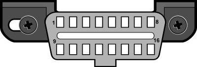
SAE J1962 standard defines two types of Diagnostic Link Connectors (DLCs): Type A and Type B. Figures 1 and 2 illustrate these connectors, with the primary distinction being the shape of the alignment tab.
DLC Location:
According to SAE J1962, the Type A DLC must be positioned within the passenger or driver’s compartment. This area is defined as being between the driver’s side of the instrument panel and extending 300 mm (approximately 1 foot) beyond the vehicle’s centerline. It should be attached to the instrument panel and easily accessible from the driver’s seat. The preferred location is between the steering column and the vehicle centerline.
Fig. 1 – J1962 Vehicle Connector, Type A
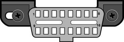
Type B DLC, in contrast, has a slightly broader allowable location. It “shall be located in the passenger or driver’s compartment in the area bounded by the driver’s end of the instrument panel, including the outer side, and an imagined line 750 mm (~2.5 ft) beyond the vehicle centerline.” Similar to Type A, it should be attached to the instrument panel and easily accessible, but accessibility is expanded to include access from the driver’s seat, co-driver’s seat, or even from outside the vehicle. The mounting of the vehicle connector should facilitate easy connection and disconnection.
Fig. 2 – J1962 Vehicle Connector, Type B
Identifying OBD2 Protocols by DLC Pinout
A practical method to identify the OBD2 protocol your vehicle employs is by examining the pinout of the DLC. Figure 3 provides a pinout diagram of the J1962 OBDII connector.
Fig. 3 – J1962F OBDII connector pinout
The table below details how to determine the protocol based on which pins are populated in the DLC:
| Pin 2 | Pin 6 | Pin 7 | Pin 10 | Pin 14 | Pin 15 | Standard |
|---|---|---|---|---|---|---|
| must have | – | – | must have | – | – | J1850 PWM |
| must have | – | – | – | – | – | J1850 VPW |
| – | – | must have | – | – | may have* | ISO9141/14230 |
| – | must have | – | – | must have | – | ISO15765 (CAN) |
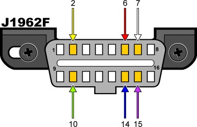
*Pin 15 (L-line) is optional in newer vehicles utilizing ISO9141-2 or ISO14230-4 protocols.
Crucially, regardless of the protocol, the connector must have pins 4 (Chassis Ground), 5 (Signal Ground), and 16 (Battery Positive). Therefore:
| Protocol | Required Pins |
|---|---|
| PWM | Pins 2, 4, 5, 10, and 16 |
| VPW | Pins 2, 4, 5, and 16, but not 10 |
| ISO | Pins 4, 5, 7, and 16. Pin 15 may or may not be present. |
| CAN | Pins 4, 5, 6, 14, and 16 |
While OBD2 standards aim for uniformity, the initial implementation allowed for manufacturer-specific choices in communication protocols before the widespread adoption of CAN. To further explore protocol usage by specific car manufacturers, resources like the OBDII Generic Communication Protocols by Manufacturer list can be invaluable. This external resource provides a detailed breakdown of which protocols were commonly used by various manufacturers during the OBD2 adoption phase. Understanding these manufacturer-specific trends can be helpful when diagnosing older vehicles or when needing to select the correct diagnostic tool and settings for a particular make and model.
In conclusion, while OBD2 provides a standardized framework for vehicle diagnostics, awareness of the different communication protocols and their historical implementation by manufacturers enhances your ability to effectively diagnose and repair vehicles. Utilizing resources that detail Obd2 Protocol By Manufacturer can further refine your diagnostic approach, ensuring compatibility and accuracy in vehicle communication.